NMSU Acousto-optic Imaging Camera (NAIC)
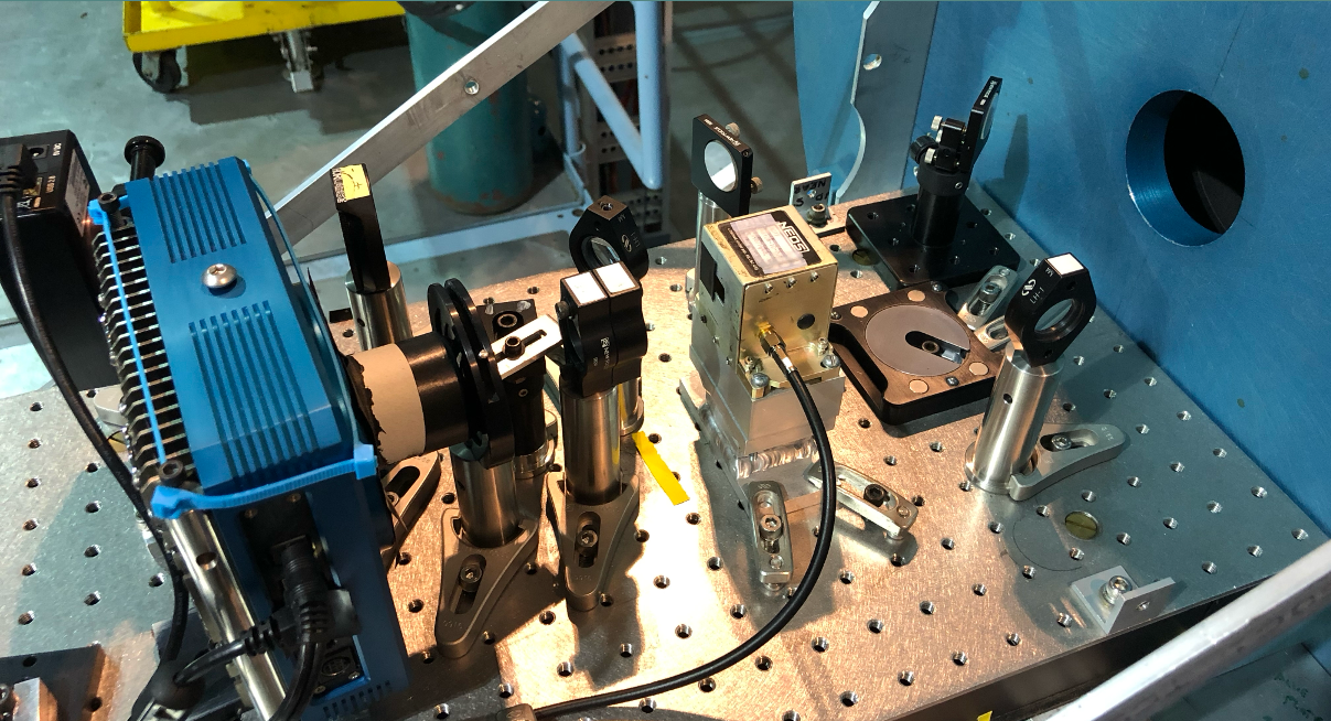
As a graduate student at New Mexico State University (NMSU) from 2015-2021, my main PhD project was an effort to observe Jupiter in the visible wavelength regime in support of the Juno mission. To complete these observations, we upgraded and reconstructed an in-house instrument called the NMSU Acousto-optic Imaging Camera (NAIC). NAIC used as its filtering element an acousto-optic tuneable filter (AOTF), which is a birefringent crystal that converts incoming light into 4 beams: two broadband beams and two diffracted narrowband beams at a slight angle. The AOTF crystal (tellerium dioxide in our case) is chosen for its high elasto-optic coefficient, such that when a standing radio-frequency (RF) wave is applied to it, the index of refraction of the crystal changes and can thus be "tuned" to emit specific wavelenghs of diffracted light, which can then be imaged by the CCD. The video below shows the view looking back through the output AOTF window as we cycled through RF frequencies quickly, filtering the light from the cal lamp.
You can find the NAIC data reduction pipeline pipeline here, a thorough discussion of the instrument in my thesis, and a paper on results from NAIC data here.
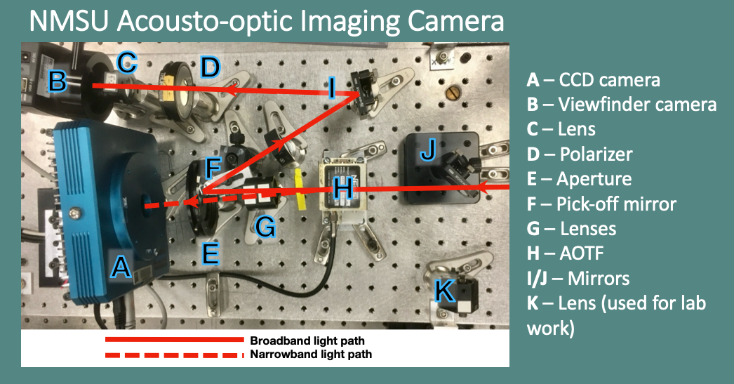
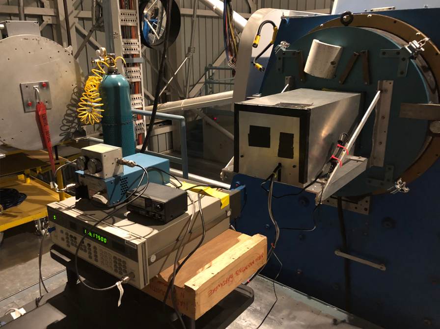
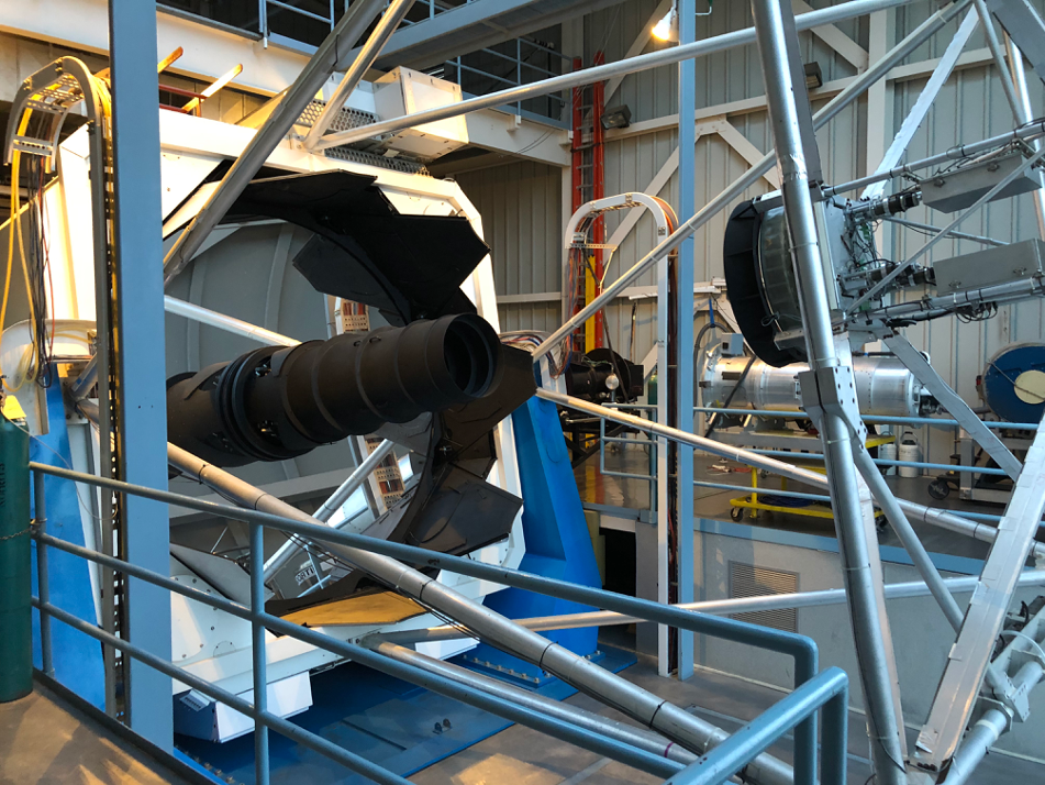
NAIC had been used by previous NMSU graduate students, but during my time at NMSU we installed a new back-buried CCD camera and the AOTF after the transducer that applied the RF wave had been repaired. Putting NAIC back together necessitated long hours in the optics lab making sure that all the optical elements of the instrument were aligned on the bench (above), that the AOTF functioned properly, that the AOTF RF power function was properly wavelength-calibrated and that the filter functions were measured correctly with a series of lasers. I took part in each step of the building, testing, and characterization of NAIC with several electrical engineering colleagues before it was ready to attach to the 3.5-m telescope at Apache Point Observatory in the nearby Sacremento Mountains (below).
Optical Etaloning and Data Reduction/Calibration Pipeline
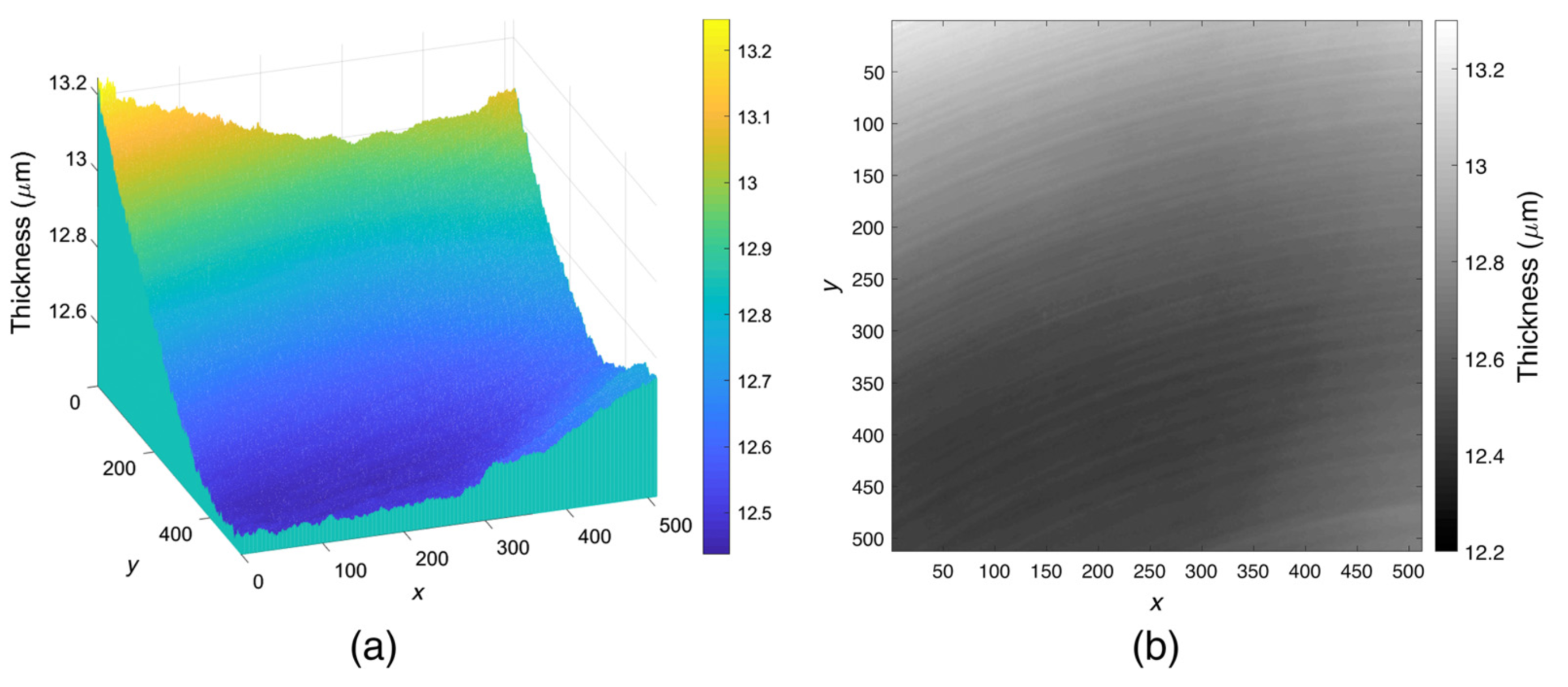
An issue that arose from the use of the back-buried CCD was optical etaloning, or the phenomenon of the silicon chip becoming more opaque at longer wavelengths and therefore causing internal relfection and "fringing" patterns. I helped our EE colleagues develop software to correct for this effect by effectively solving for the thicknes function of the silicon chip and modeling artificial, normalized fringing frames, wihch were then used prior to flat division to divide out the fringing signature. See the below left video for a prototype of this model that I developed, which shows the fringing pattern intensities resulting from different wavelengths for a given chip shape. The final derived chip shape and thickness function are to the right, from Wijerathna et al. 2020. You can read more about this optical etaloning correction software here.
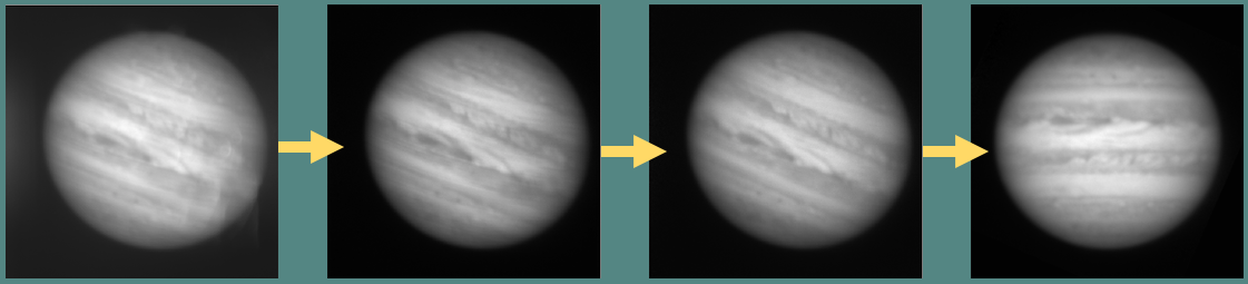
Another large task I completed as a PhD student was writing a full Python-based photometric calibration and reduction pipeline (see illustration of scattered light subtraction, fringe removal, flat division, and alignment steps below) for our NAIC hyperspectral image cubes of Jupiter. You can find the pipeline here, a thorough discussion of the steps in my thesis, and a paper on results from NAIC data here.